ACCAT - Advanced Circuit Card Automated Test by PIDESO and Huntron (click image to enlarge)
The ACCAT is designed to support diagnostic and acceptance test requirements across a wide spectrum of testing parameters.
ACCAT provides a suite of core parametric test instruments, advanced GUI based software, Huntron Access Robotic probing and
Huntron Analog Signature Analysis (ASA).
ACCAT provides stimulus and measurement capabilities necessary for full functional and parametric testing
of circuit card assemblies along with robotic guided probes for fault verification and debug.
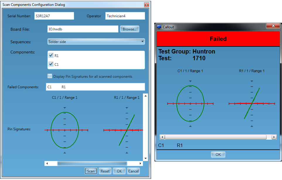
The Huntron ASA test is ideal for pretest or safe to power up procedures protecting the integrity of the test system.
Reducing time to test and increasing fault coverage leverages the best features of functional and power off testing.
ITAs are quickly developed for the circuit card reducing time to test.
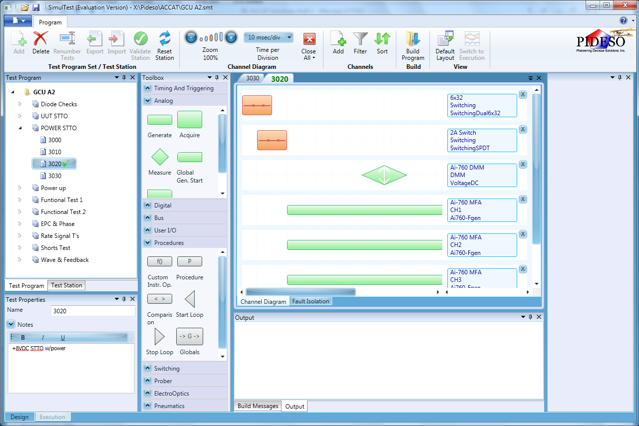
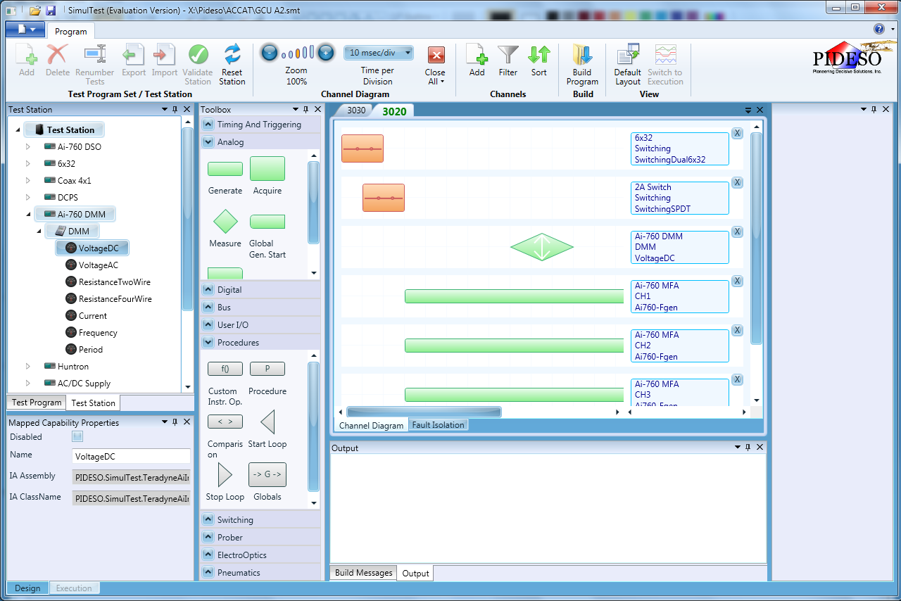
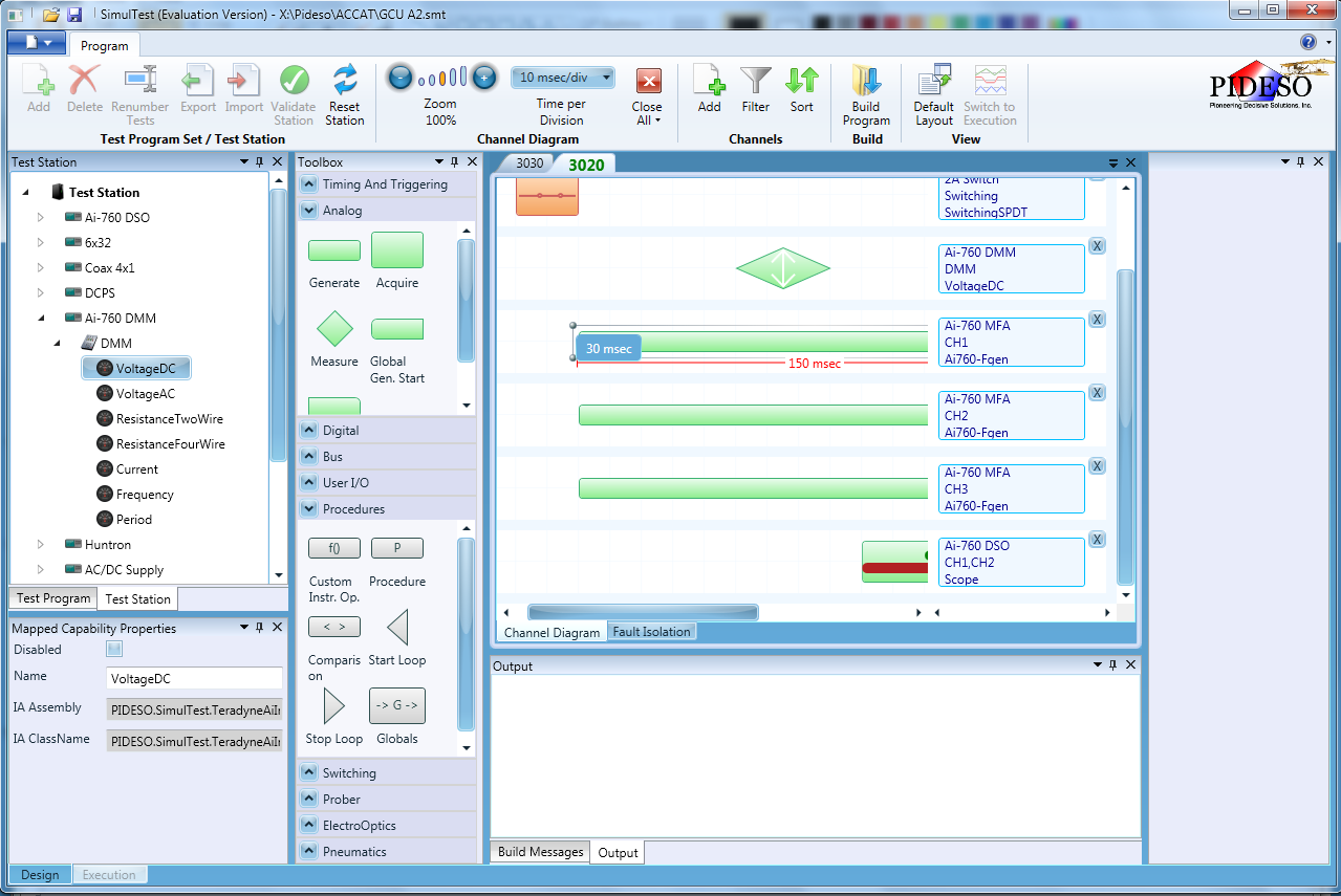
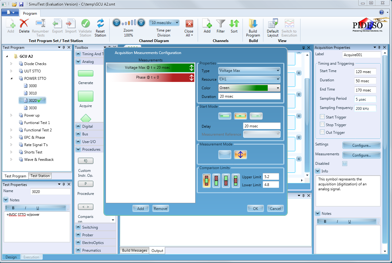
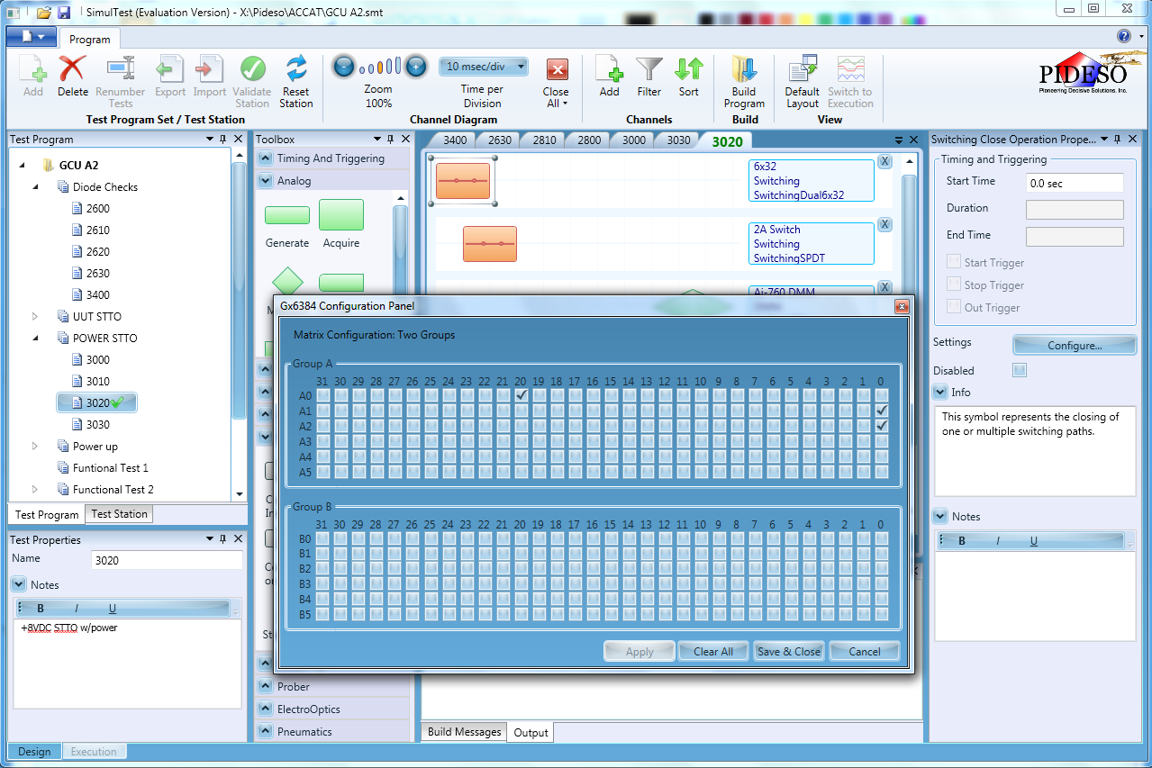
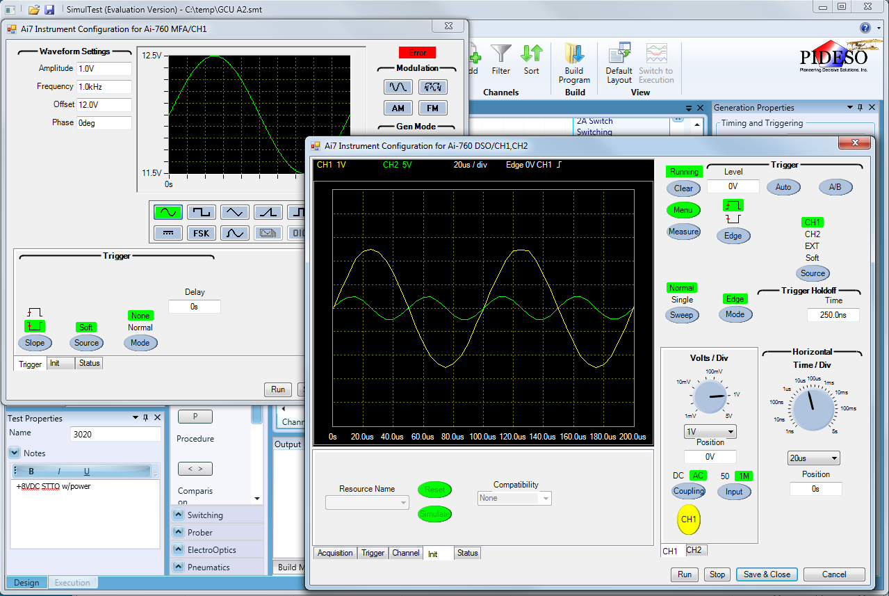
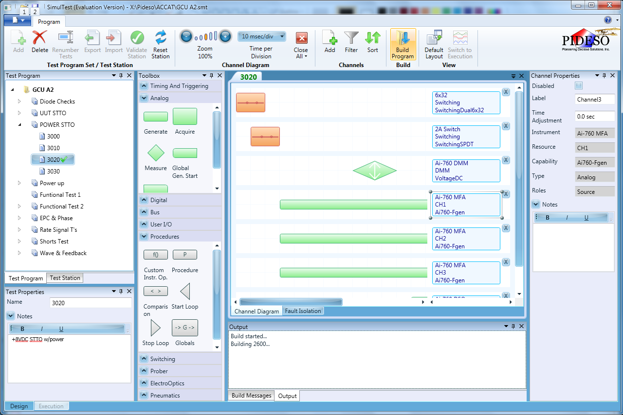
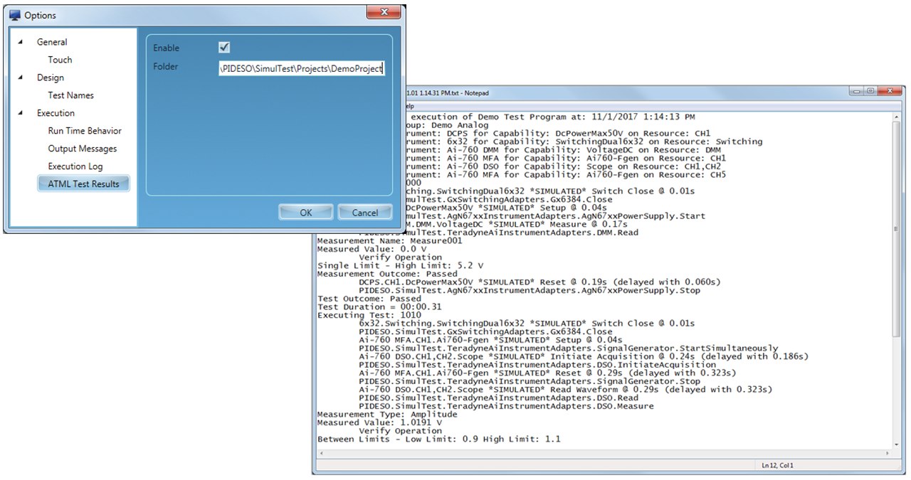
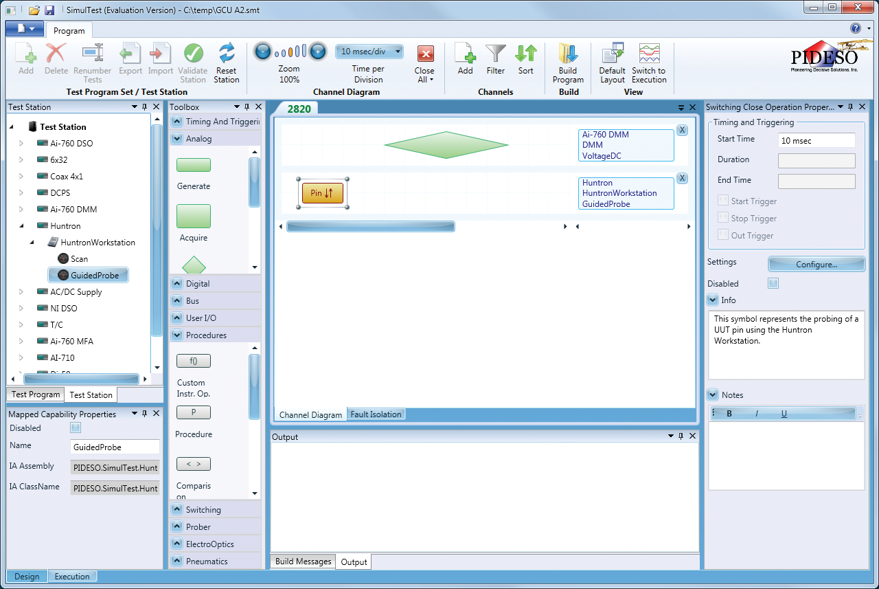
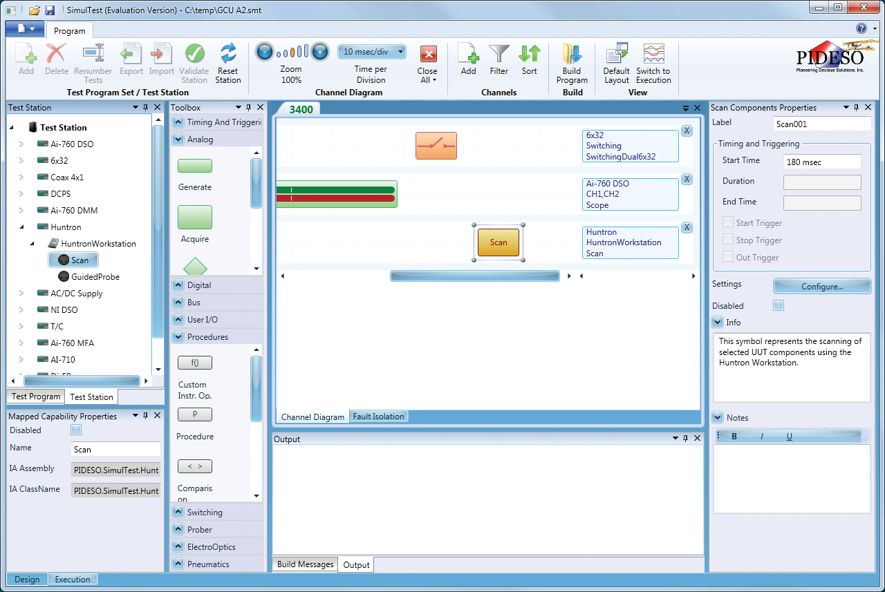
SimulTest®
drag and drop graphical test development environment enables engineers and trained technicians to easily create
simple or complex test procedures.
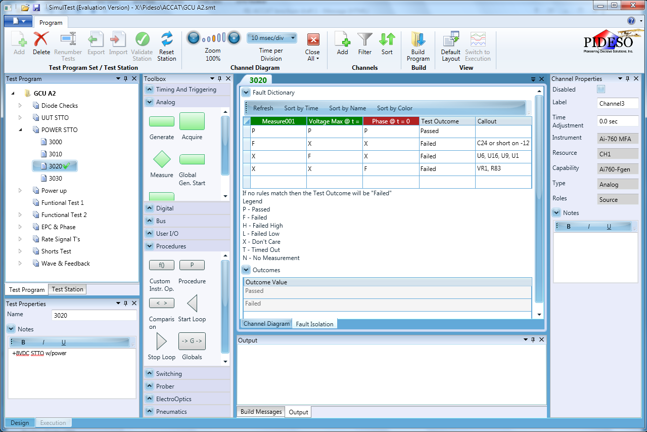
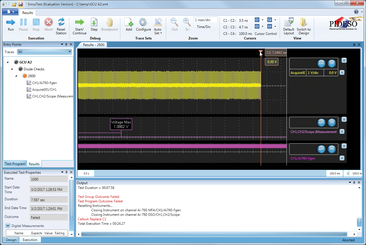
ACCAT with SimulTest coherent graphical results display and Failure Isolation Matrix make diagnostics more powerful than standalone ATE.
Adding automatic guided probes to functional test provides unique I/O and measurement possibilities as well as diagnostics.
Complete end-to-end testing without technician intervention.
Use power-off ASA diagnostics for safe-to-turn-on and ambiguity group test.
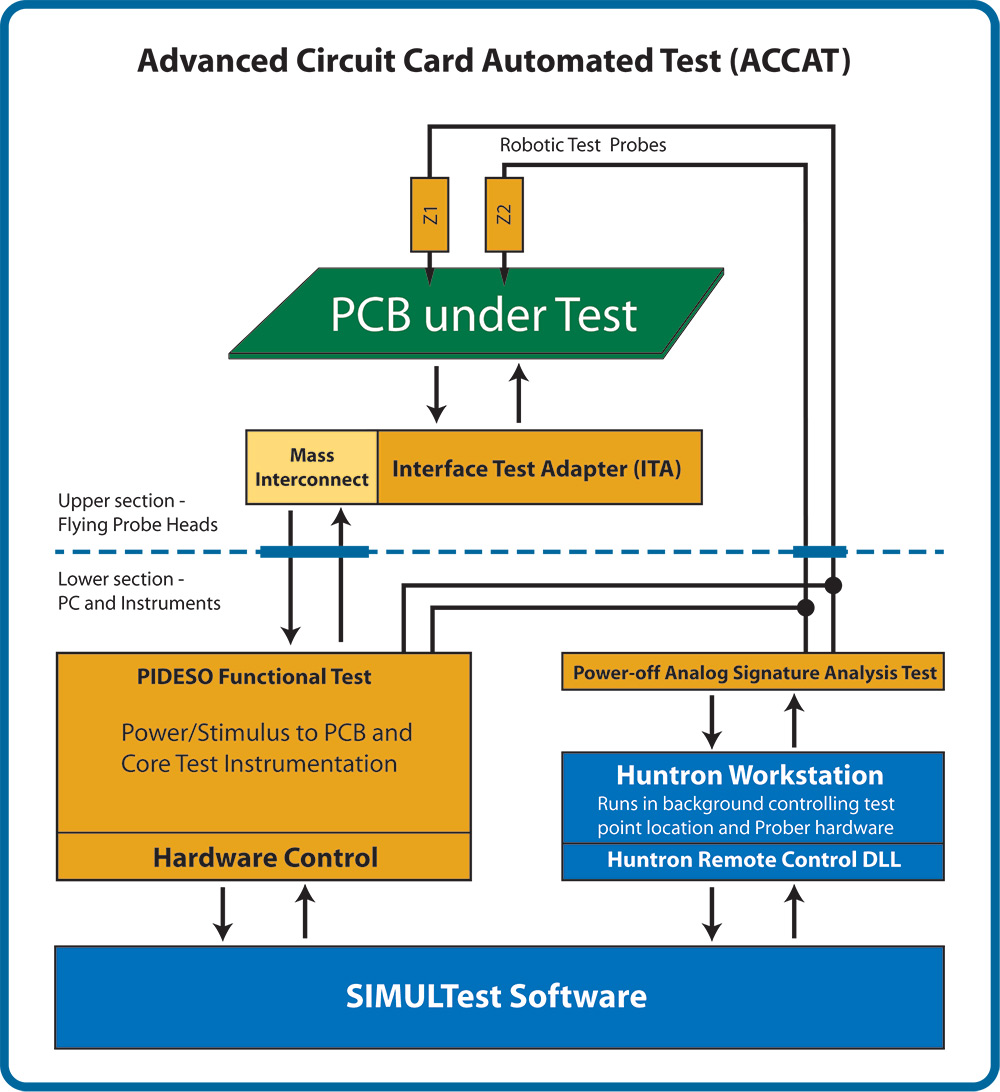
ACCAT - Block diagram overview (click image to enlarge)
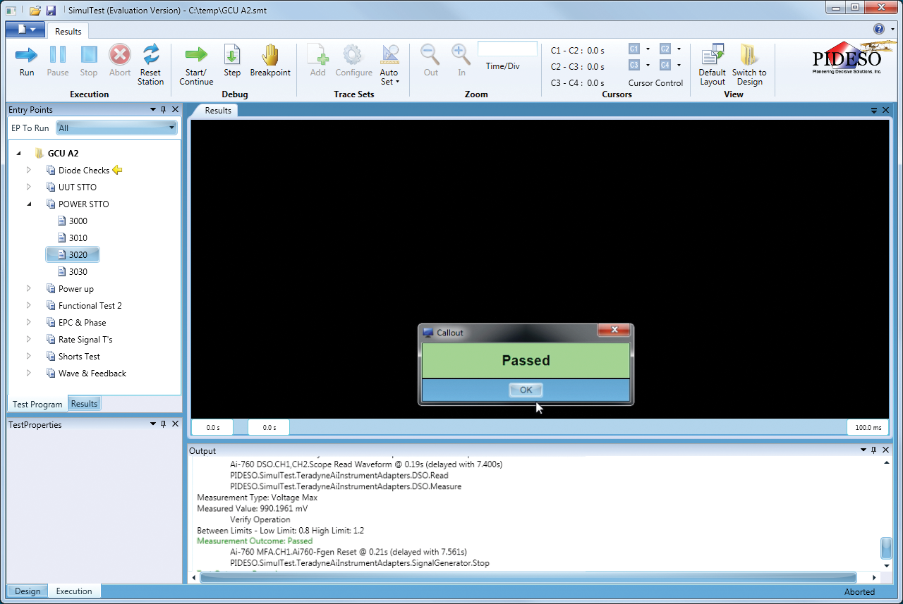
SimulTest software will functionally test and evaluate the circuit card for compliance with operational specifications.
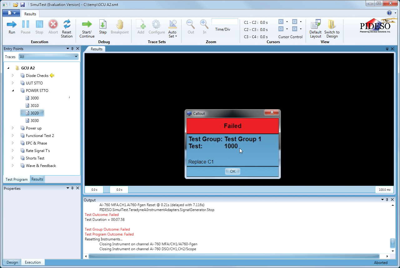
Combining SimulTest and the Huntron Workstation, every accessible test point, component pin, or via can be targeted for automated probing.
SimulTest branches to fault ambiguity groups and places the probes in position to measure in the most logical order to identify the fault
Utilizes the
Access DH2 Prober
to automate the testing of accessible points.
Durable, standalone cabinet design for many years of service
Built-in side by side 19" racks provides plenty of space for PC and integrated test instrumentation
ITAs use standard S6 interfaces from Virginia Panel
Configured with Huntron Analog Signature Analysis for power-off diagnostics
Test Program Set (TPS) development available from PIDESO
Huntron and PIDESO - Strategic Partners
Huntron
and
Pioneering Decisive Solutions (PIDESO)
have joined together to develop the versatile ACCAT system that combines the best of circuit card testing technology.
Huntron is a supplier of tools for engineers and technicians who test, diagnose and troubleshoot printed circuit cards.
Founded in 1976 with the introduction of the Huntron Tracker, Huntron has developed robotic automation tools to help deal
with the increase in board complexity and help users save valuable time.
Since 2006,
PIDESO
has built and maintained its professional reputation as an innovative technical leader.
They specialize in development, fielding and life cycle logistics support for military and
commercial Automated Test Systems, Test Program Sets and AT Systems capability.
SimulTest Tour
The ACCAT instruments controlled by the PIDESO SimulTest software will functionally test and evaluate the circuit card
for compliance with operational specfications.
SimulTest Slide Show
You can view an image based tour of SimulTest by clickng the image to the left.
The images will pop up into an on-screen slide show.
Use the
ARROW
buttons that appear on each side of the displayed image to move forward or backwards through the slideshow.
Descriptive captions will appear below each image.
ACCAT Prober Specification
Number of Test Heads
2
Maximum Board Under Test Size
27" x 23" (68.6cm x 58cm)
Maximum Probing Area
19" x 12" (48.3cm x 30.5cm)
Maximum Board Component Height
3" (7.6cm)
Accuracy and Resolution
0.0003937" (±10 microns) for Top Slot (6" above plate) at 0.00002" (0.4 microns)
Interface Test Adapter (ITA) Specifications
Type
Virginia Panel S6 Slide mass interconnect and adapter
Maximum number of pins
1440 maximum
Configuration
Horizontal 1U low profile with positive lock latching system
Supported ACCAT Test Instruments
Digital Subsystem
50 MHz 30V 1ns 64-Channel Card Digital Instrument
Manufacturers: Marvin Test, National Instruments, Teradyne
Function Generator, Arbitrary Waveform Generator, Digitizer, DMM, Limit Detector, Time Counter
Manufacturers: Marvin Test, National Instruments, Teradyne
Programmable DC Power
Power supply chassis 600W (1200W with 220VAC Option)
Manufacturers: Keysight
Programmable AC Power
3 Phase Precision Programmable AC Source (220VAC Option)
Manufacturers: California Instruments
Switch Matrix
Dual 32x4 or 64x4 Configuration (256 cross points)
Manufacturers: Marvin Test, National Instruments
Coax Multiplexer
20 channel Four 1x4 Multiplexer
Manufacturers: Marvin Test, National Instruments
Huntron Tracker
24 Voltage ranges (200mV-20V); 16 Resistance ranges (10-100K Ohms); 40 Frequency ranges (20Hz-5KHz)
ACCAT System General Specifications
Power requirements
115-230VAC
Dimensions
47” W x 61.5” H x 35.75” D (w/handle) (119.4cm W x 156.2cm H x 90.8cm D)
Cabinet Internal Dimensions
45" W x 29" H x 33" D (114.3cm W x 73.6cm H x 83.8cm D)
ACCAT System FAQ
Q: What is the standard base instrumentation configuration?
A: The standard ACCAT configuration (subject to change):
64 channels of dynamic digital
4 DC power supplies 1 0-35VDC; 2 0-50VDC (1 High Performance; 1 Precision) ; 1 0-150VDC
3 Phase AC/DC supply 0-400V 0-2000Hz
2 Channel 1Gs/s Digital Oscilloscope
Digital Mulitmeter
2 Two Channel Arbitrary/Function Generators
Dual 6x32 Matrix Switch (384 Crosspoint)
25 channel 2Amp SPST Switch
4 Channel 4x1 Coax Switch
Huntron Access DH2 Dual Head Prober
Huntron Access Tracker
Q: Can I request a custom testing configuration?
A: Absolutely. The ACCAT instrumentation package can be customized to meet your testing needs.
Q: How much time is needed to build a TPS?
A: The test program set (TPS) creation time depends on the circuit card complexity, available documentation and ITA complexity.
In general, a typical TPS could be created in roughly 4 weeks.
Q: What is required to build a TPS?
A: Information on the circuit card assembly (CCA) that is required would be an I/O table (describes the signals on accessible pins) and
information on how the CCA is used in the next higher assembly.
Schematics, testing procedures and an illustarted parts breakdown would prove very useful as well.
Q: How long does it take for a TPS to run?
A: A typical run time for a TPS using 200 test steps would be about 10 minutes.
Q: How fast is the ACCAT Flying Prober section?
A: The probing speed depends on how the Prober is being used.
If it is being used to take measurements, the speed in affected by how long it takes to capture the measurement.
In general, you will be able to probe one point approximately every two seconds.
Q: How accurate is the ACCAT Flying Prober and how close can the probes get to each other?
A: The ACCAT is very accurate. The minimum step resolution is 0.4 microns with an accuracy of +/- 20 microns.
This is more than accurate enough to probe very small lead spaced devices such as the 0.4mm surface mounted ICs.
Currently, the minimum spacing between the two probes is 0.05" (1.27mm) when 50mil probe holders are installed.